Cross Sections Editor#
This section will cover many of the tools available to develop channels for FLO-2D. This is not a step-by-step procedure. It is a compilation and detailed outline of the tools available and how to use them. For step-by-step instructions, see the workshop lessons.
Channels#
Identify the Channel#
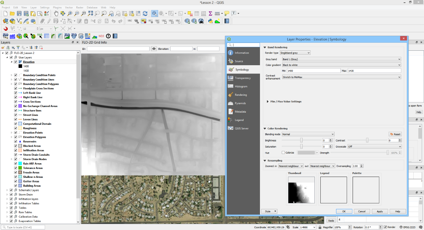
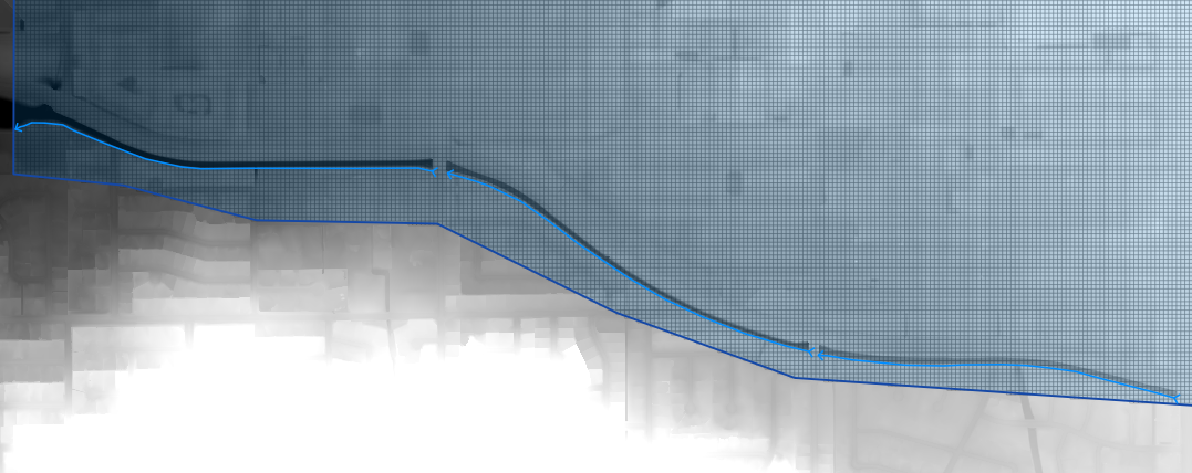
The elevation raster style can be edited so that the channel is well defined. Adjust the min / max view setting to enhance the channel depth.
Left Bank#
Select the Left Bank Line layer.
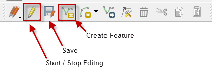
Click on both the start editing button and the add feature button.
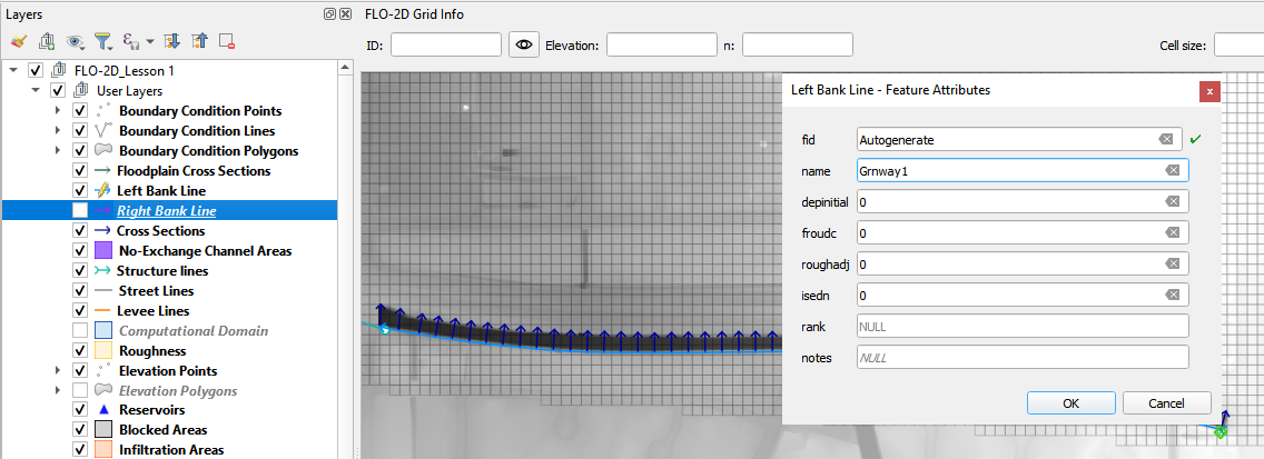
Create a polyline to represent the left bank looking downstream and click to save the layer.
It is important to create the segments from order upstream to downstream.
Tributaries or split channels should be created once the main channels are complete.
Repeat the process for the all the various channel segments and save.
Right Bank#
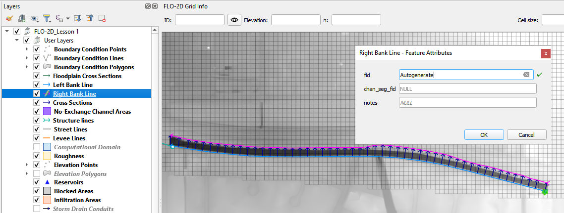
Select the Right Bank Line layer.
Click on both the start editing button and the add feature button.
Create a polyline to represent the right bank looking downstream and click to save the layer.
It is important to create the segments from order upstream to downstream.
Tributaries or split channels should be created once the main channels are complete.
Repeat the process for the all the various channel segments and save.
Natural Cross Sections#
To create natural cross sections, the cross sections should be numbered consecutively from upstream to downstream for each channel segment.
Click the Add Cross sections lines button.
Digitize the cross section on the map.
Name the cross section and click OK to finish the feature.
Click save to complete the process and load the data into the widget.
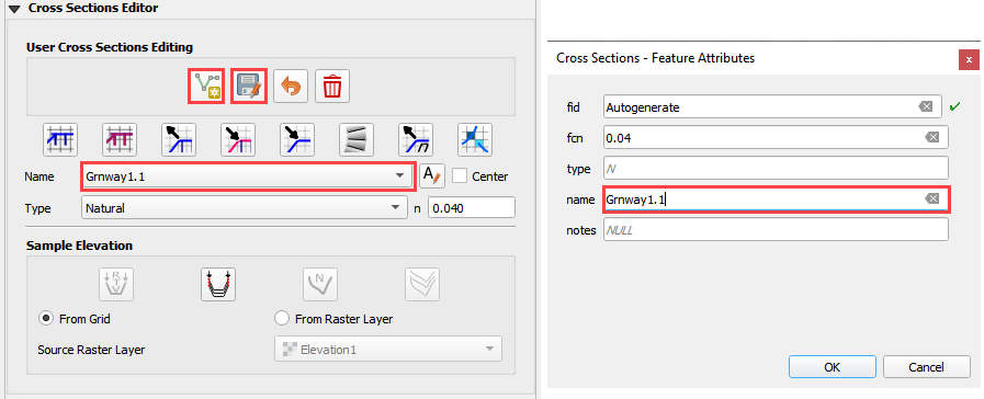
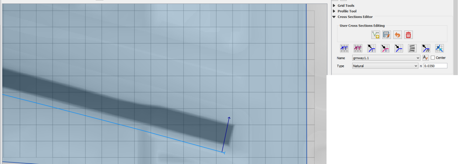
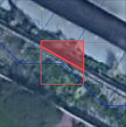
The cross sections shown in the following image have been digitized.
Important Notes:
Draw polylines from left bank to right bank looking downstream.
The first cross section must cross the left and right bank and be inside the same grid elements.
The subsequent cross sections can cross the left and right bank and be wider than the channel.
Place-holder data is added to the cross section station elevation data. It is replaced after all cross sections are ready.
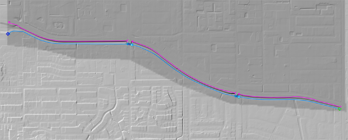
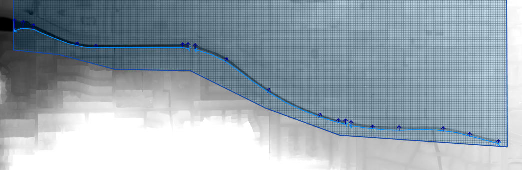
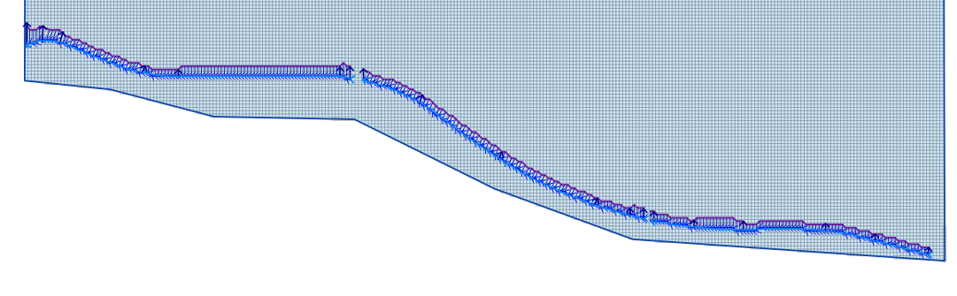
The finished product will look something like the following image.
Cross Section Bank and Station Elevation Tool#
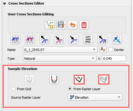
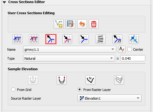
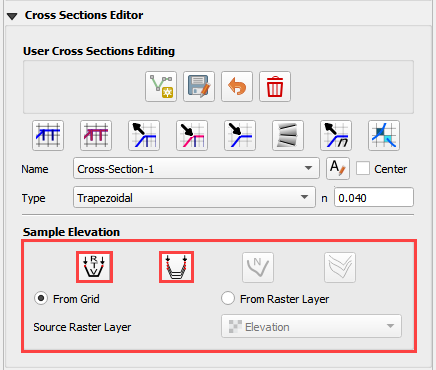
The preferred and easiest way to sample elevation data for a cross section is by using the FLO-2D Sample Elevation tool. Once the cross sections are digitized onto the map, the Sample Elevation tools are used to sample elevation data from a raster into Stations/Elevation data sets for all or individual cross sections.
This section will focus on N type or natural channel geometry.
Set the elevation raster as the Source Raster Layer and use either button to sample one or all cross sections.
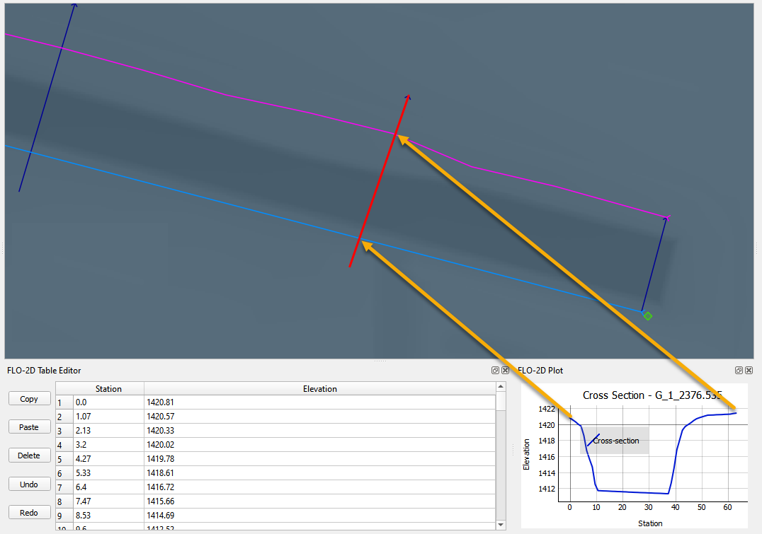
The station elevation data is limited to the point where the left and right bank intersect the cross section.
If too much or too little data has been sampled, adjust the left or right bank alignment and sample the elevation again.
Schematize Channel#
Once the banks and cross sections are complete, the next step is to Schematize the channels. Click the Schematize left banks and cross sections.
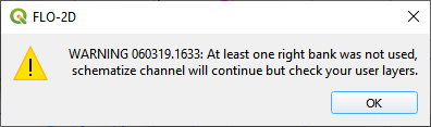
Errors and warning will appear if something is not configured correctly.
At the beginning of each segment, the left bank node, right bank node must be in the same cell as the end nodes on the cross sections.
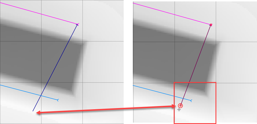
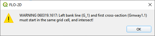
If the cross section does not touch the left or right bank, the following message will appear.
Correct this condition by making sure each cross section crosses both banks.
If the channel schematize process was successful, the following message will appear.
Click close to load the channel info for the schematized layer.
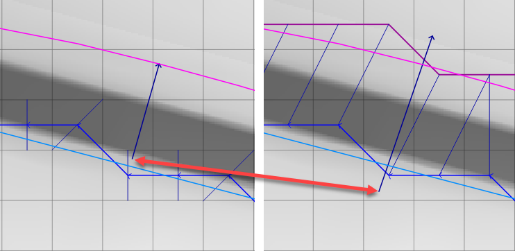
The schematized layers now have complete left bank, right bank, and cross section data. Adjust cross section and left bank alignment now. It is easier apply changes before interpolating the cross section data.
Interpolate Natural Channel#
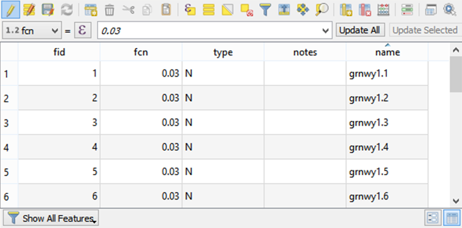
Inspect the cross section n-value field to ensure all n-values are present. If missing, fill the required n-value to the field.
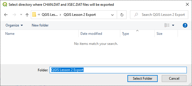
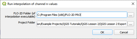
To interpolate the channel segments, export the channel data and run the interpolator.
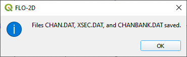
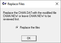
Select the folder where the *.DAT files will be saved.
Once the data files are written, click ok to close the following dialog box.
Select the FLO-2D Pro Folder and click Interpolate.
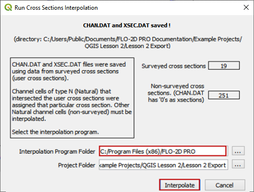
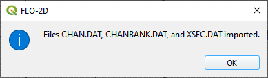
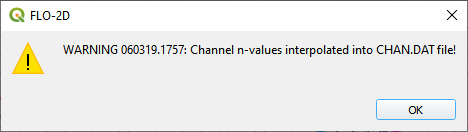
If the interpolation is performed correctly, the following message will appear. Get the new data into the GeoPackage by clicking Import CHAN.DAT, AND XSEC.DAT.
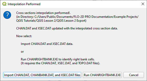
Click OK to close the message.
Prismatic Cross Sections#
Prismatic channel data can be entered and interpolated using the cross section editor. Use this option for creating Rectangular and Trapezoidal channel segments. This example will use two segments of channel data. One for a rectangular channel and one for a trapezoidal channel.
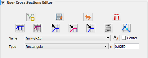
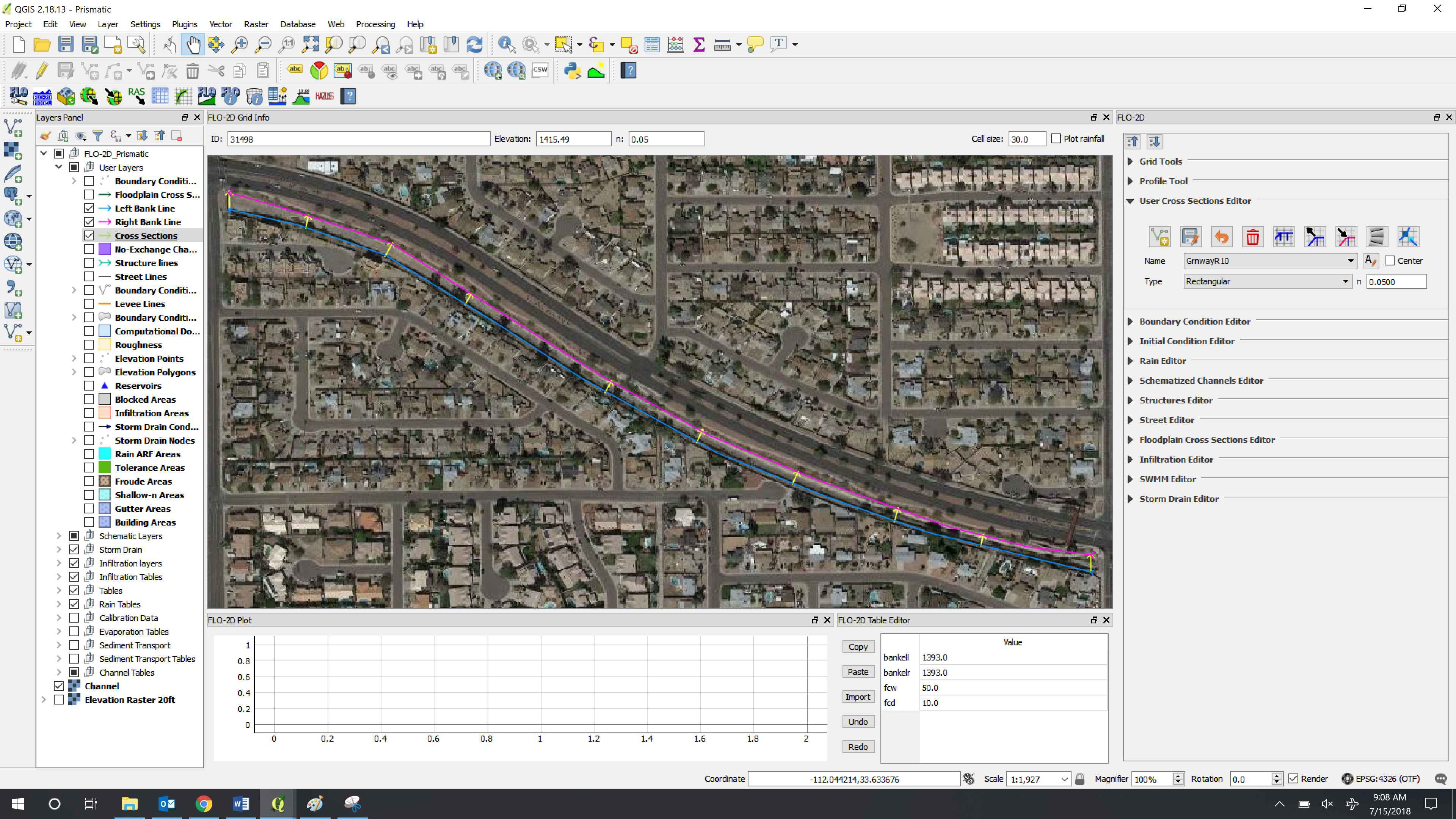
Rectangular Cross Sections#
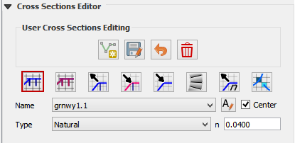
Set up the Editor Widget. Type = Rectangular base n = 0.020
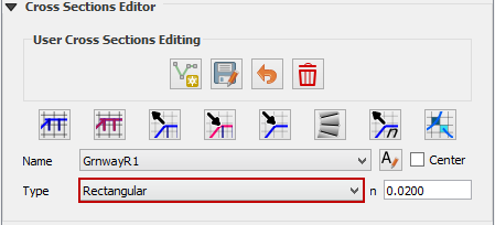
Click the create cross section button.

Draw the first cross section and enter the Feature Attributes. See Sample bank data to
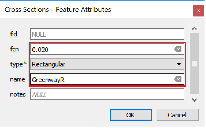
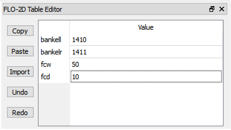
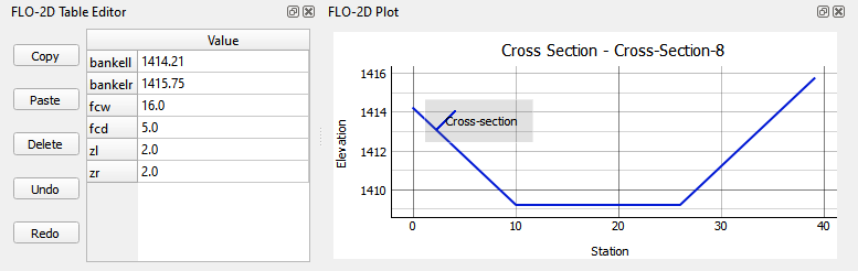
Click Save to load the cross section into the Table Editor.
Edit the cross section left and right bank elevation and geometry in the table. Repeat the process for each cross section. See Sample bank data to learn how to fill this data automatically.
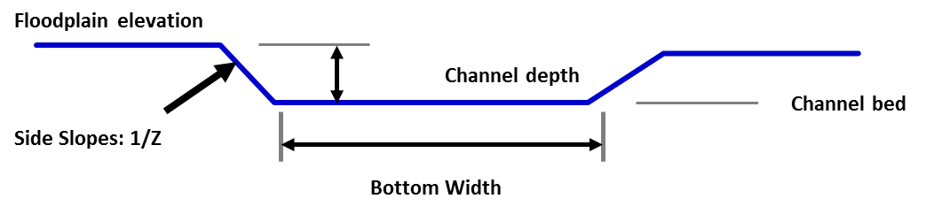
Trapezoidal Cross Sections#
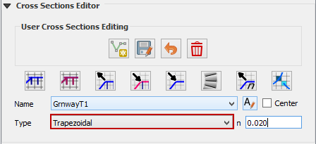
Set up the Editor Widget. Type = Trapezoidal base n = 0.020
Click the create cross section button.
Draw the first cross section and enter the Feature Attributes.
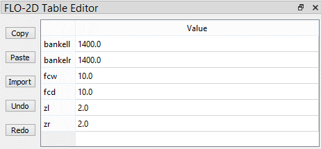
Click Save to load the cross section into the Table Editor.
Edit the cross section left and right bank elevation and geometry in the table. Repeat the process for each cross section. See Sample bank data to learn how to fill this data automatically.
Schematize Rectangular and Trapezoidal Channel Segment#
In this example, ten Rectangular, ten Trapezoidal and 10 natural cross sections are digitized.
Click the Schematize button.

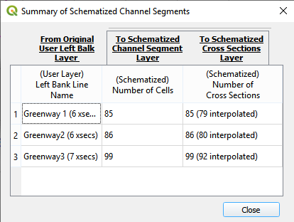
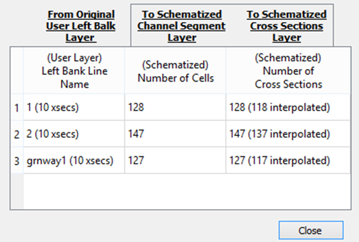
If the following message appears, the schematization worked properly.
This dialog box shows the number of original cross sections and the number of schematized cross sections.
Sample Bank Data#
There are many ways to edit the bank data for R and T type channels. This section will show two different ways to create and correct bank elevation data.
The bank elevation data can be sampled in two methods.
Method 1: Elevation from Grid#
The first method is from the Grid layer and the second is from the elevation Raster.
Click the From Grid radio button and select Individual or all cross sections to sample.
The bank data is the reference point to determine the bed elevation of the channel so it can influence the profile. For example, if one uses the grid element elevation to set the bank elevation, the channel profile is wrong. The Grid method should only be used if a good raster is not available.
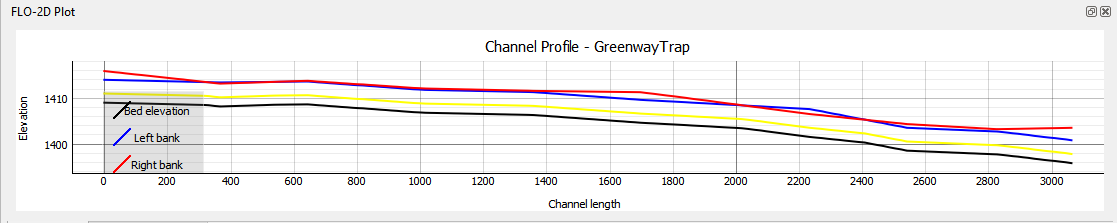
Click the channel profile tool and the left bank to check the profile of the channel.

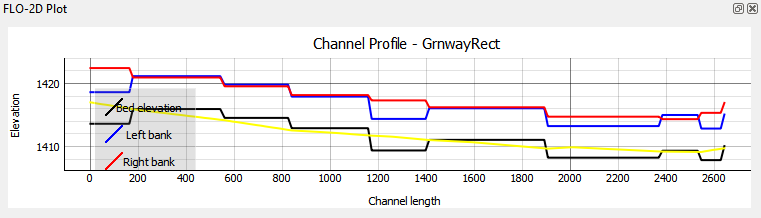
This is not the preferred method since a grid elevation for a grid is always somewhere in between the bank of the channel and the internal channel data.
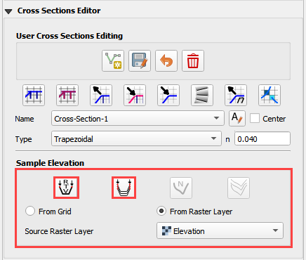
Method 2: Elevation from Raster#
This method is used if an elevation raster can be used to define the bank elevation.
Click the From Raster radio button and select Individual or all cross sections to sample.
Interpolate Prismatic Channel Data#
Finish the cross sections and layer organization of the trapezoidal and or rectangular channels.
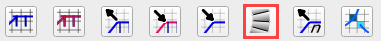
Click the Interpolate button to interpolate the left and right bank of the rectangular channel.
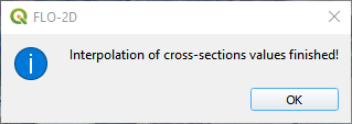
If the process finished correctly, the following box will appear. Click OK to close the box.
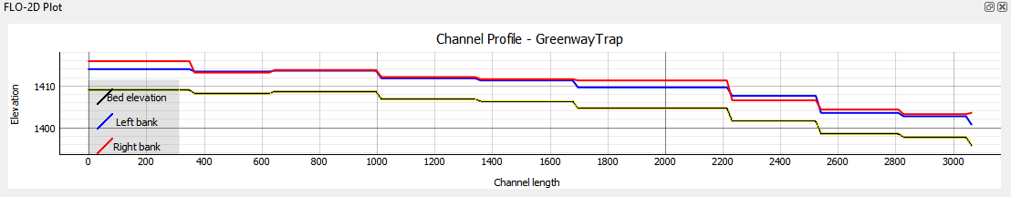
Click the channel profile tool and the left bank to check the profile of the channel.
Channel N-value Interpolator#
The channel n-Value interpolator tool is used to define the n-value of a channel cross section based on the cross section geometry.
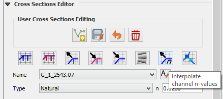
The button calls the tool externally.
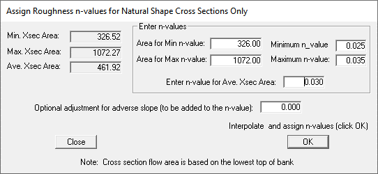
The tool assigns an n-value for the chan.dat file based on the picture below. The user can choose the n-values for a minimum or maximum cross section area.
Alternate Bank and Channel Profile Tool#
A secondary method can be used to create the cross section data. This example will sample the map for station-elevation data using a Plugin called Profile Tool. This tool is not the preferred method but it has some handy features that make it useful.
Find and install the Plugin Profile Tool.
Select the first cross section in the Cross Section Editor widget. This activates the cross section table and plot.
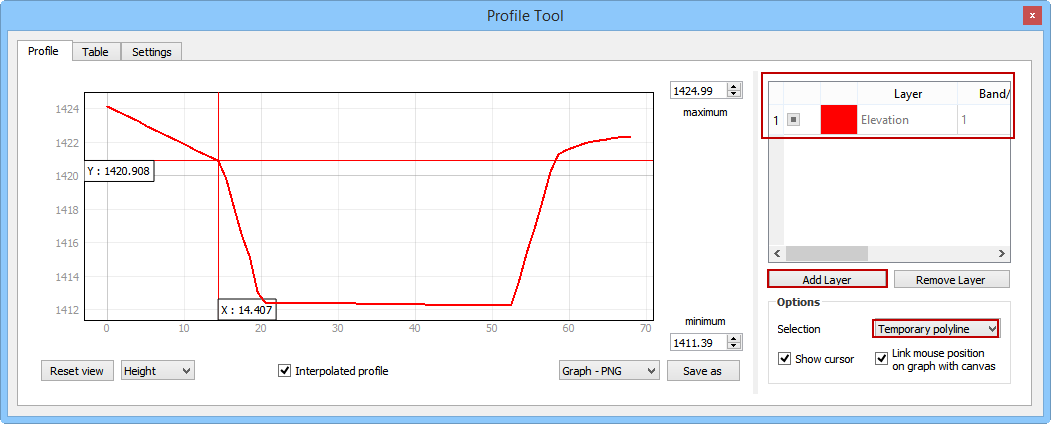
Click the Profile button to open the Profile Tool Plugin,
Click the add layer button and select the Elevation Raster layer.
Draw a simple line over cross section 1.
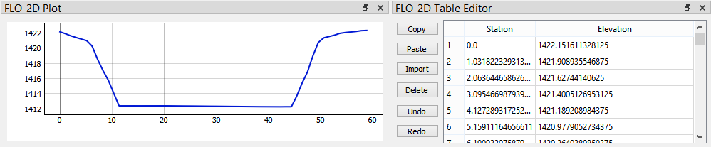
The cross section station elevation data is listed in the Table tab shown below. Copy it to the clipboard.
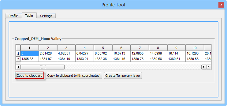
Place the cursor in the first cell of the FLO-2D Table Editor and click Paste.
The cross section data is pasted to the table.
Repeat the process for the remaining cross sections.
The cross section is then loaded in the layer as shown below.