Levees Breach Editor#
Breach Prescribed#
This tool will define a single breach location. If walls are being designed, use the Levee and Wall method not this method.
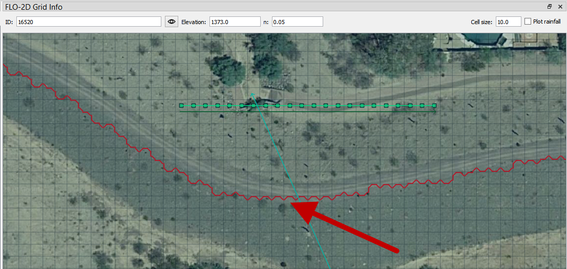
Use the Grid ID tool to pick the levee element to assign a prescribed breach to.

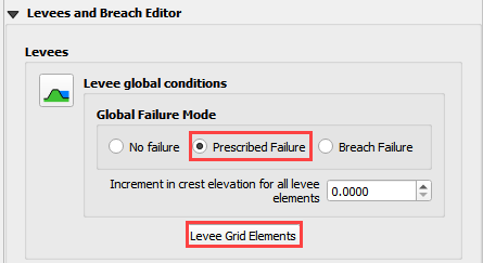
From the Levees and Breach Editor, click Prescribed Failure radio button and then click the Levee Grid Elements button.
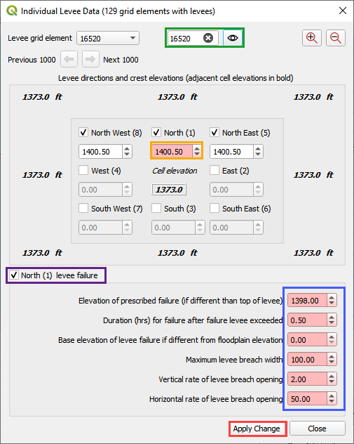
The process to apply levee prescribed breach:
Add the grid element number of the levee that will initiate the failure. Press the eye button. (Green)
Place the cursor into the levee elevation combo. (Orange)
Check the Failure check box. (Purple)
Fill the failure criteria. See Data Input Manual for variables use. (Blue)
Click Apply Change. (Red)
Close the dialog box after clicking Apply.
Breach Erosion#
FLO-2D has embedded the Fread BREACH earthen dam breach and erosion model.
Fread, D. (1988). BREACH: An erosion model for earthen dam failures.
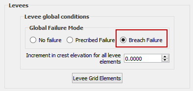
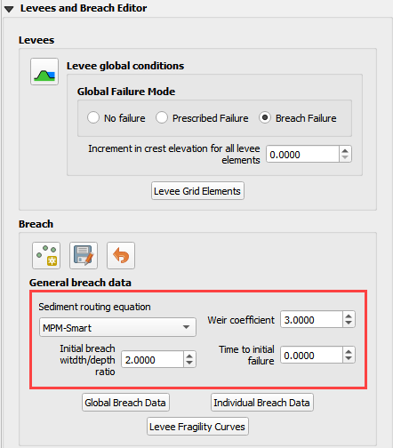
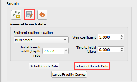
To create Breach Erosion data for this tool, set the Failure Mode to Breach Failure. This action will activate the Breach widget.
The General breach data is set in the Breach Widget. Fill the boxes below.
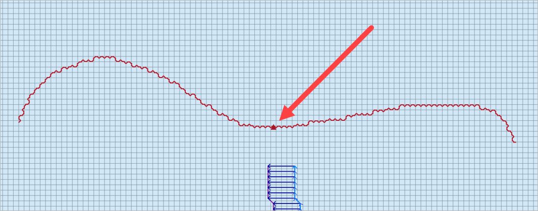
Use the Point button to create a Dam Breach Node. Click the button and then click the breach location on the map.
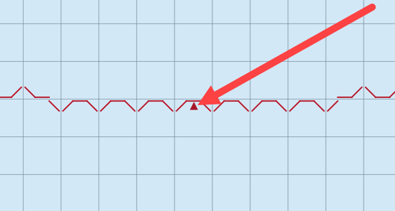
It is important to apply the breach to the reservoir side of the levee. Do not apply a breach point on the downstream side of the levee. In this case, the breach starts in the North direction because the Point is closest to that levee.
Click this location.
Click OK to close the Dialog box. It is not necessary to fill the data here.
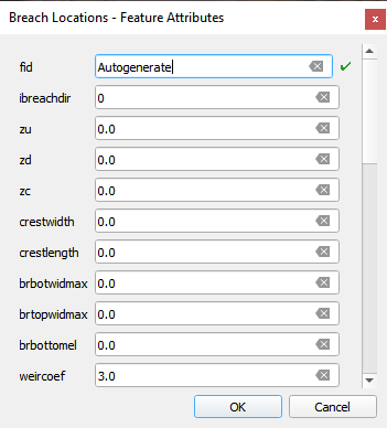
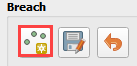
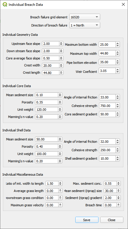
Click the Save button on the Breach Widget activate the breach editor. Click the Individual Breach Data Button to fill the dam and breach data into the dialog box.
This dialog box is used to define the followoing data. For more information see the Data Input Manual and the Erosion Breach Tutorial.
Dam geometry
Geotechnical soil data
Breach methodology data
Fill the box and click Save.
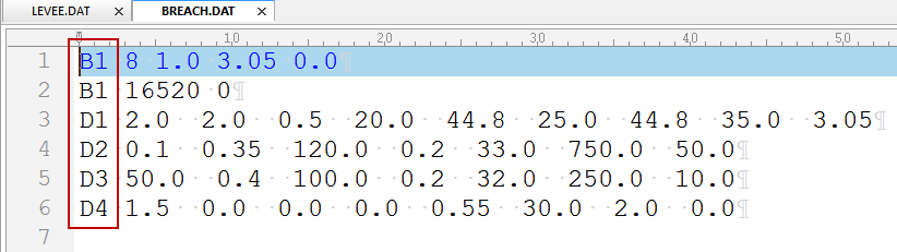
Export the data and check the BREACH.DAT and LEVEE.DAT data files.

LEVEE.DAT should include the Breach Erosion Switch.
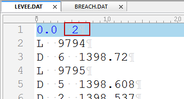
BREACH.DAT should have only the B lines and D lines for general and individual breach data.
Important notes for Dam Breach Modeling.
The cell elevation should be reset to the base floodplain elevation for any cell that represents the breach flow path. See the Elevation Correction section for more details.
The breach node should be assigned to a node with a levee and the breach direction should be set so that the breach occurs in the downstream direction.
It is also important to choose a flow direction that contains a levee cutoff.
The levee crest elevation is used as the dam crest elevation. The base elevation is set by the levee cells where the breach occurs.